This is an unmaintained course material, please see current material at:
Analysis of processing outputs
GIS595/MEA792: UAV/lidar Data Analytics
NCSU
OSGeoREL
at
Center for Geospatial Analytics
Fall 2015
Objectives
- Understand how to interpret a processing report
- Compare errors and survey data from different flights
- Recognize differences in geoprocessing products generated by different softwares
- Understand significance of using GCPs in the processing and their impact on the final products
- Recognize what processing steps need to be modified in order to improve particular errors
- Understand what causes the 'Bolw effect' and know the solutions to fix it.
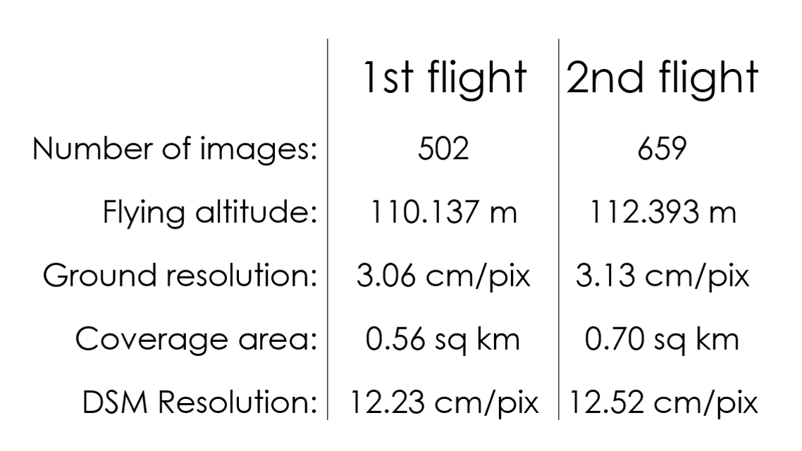
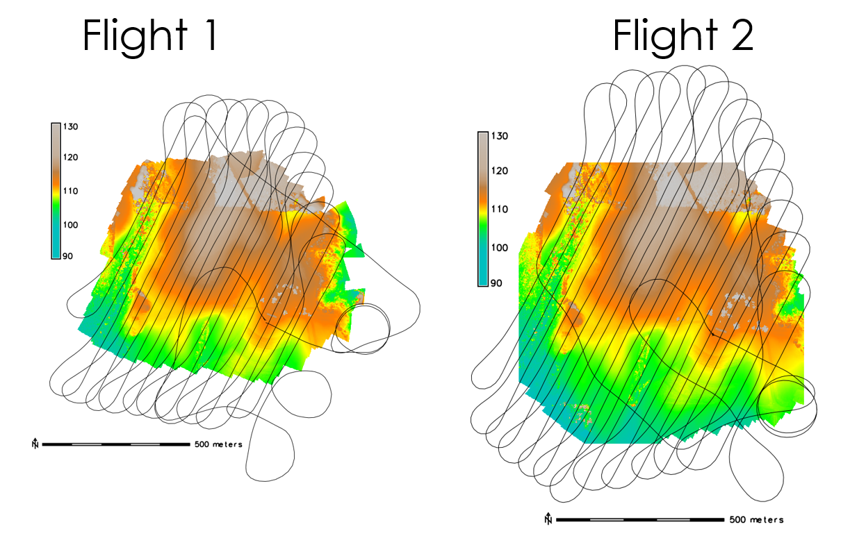
Flights Oct. 6th 2015
Flights Oct. 6th 2015
Analyzing the processing report
Includes:
- Orthophoto and digital elevation model sketch;
- Camera parameters and survey scheme
- Tie points data export (matching points and panoramas)
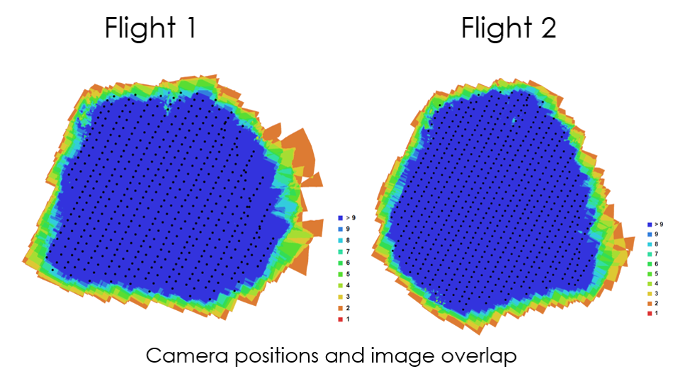
- Image overlap statistics
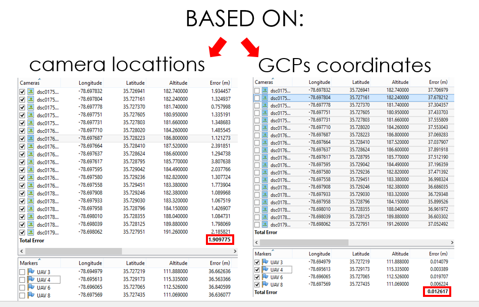
- Camera positioning error estimates
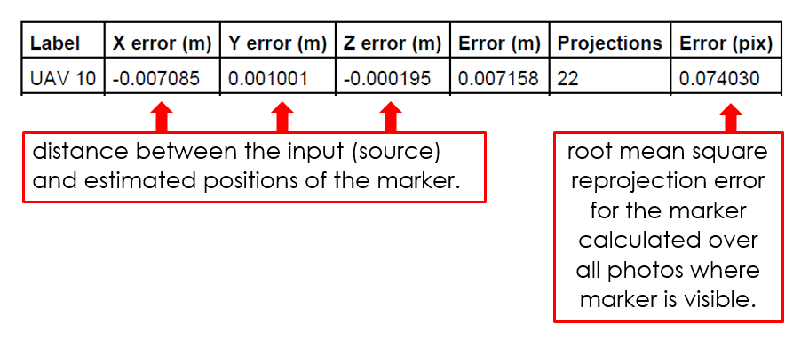
- Ground control point error estimates
Orthophoto
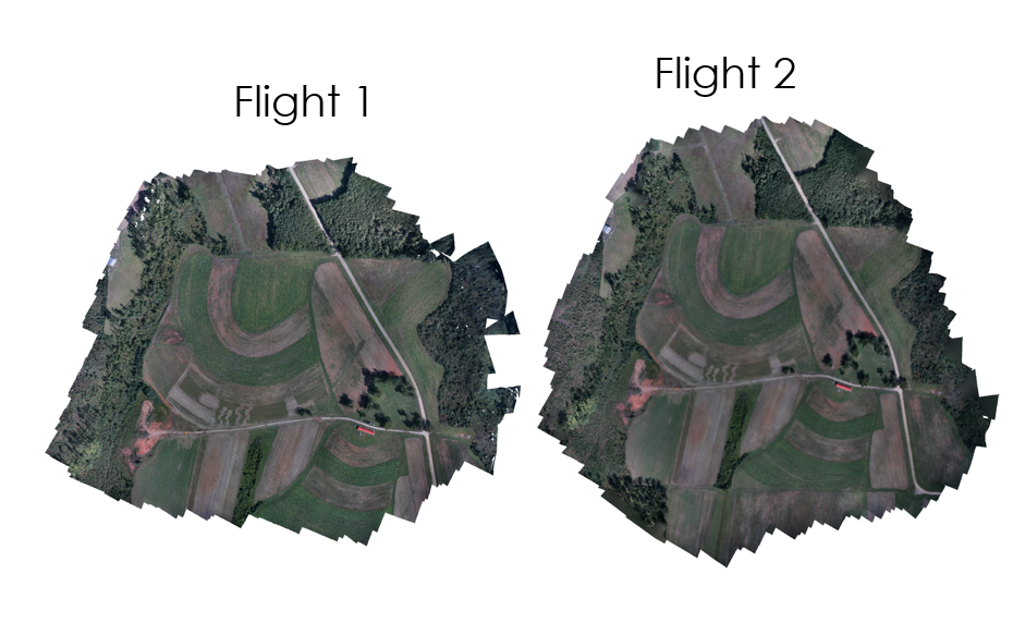
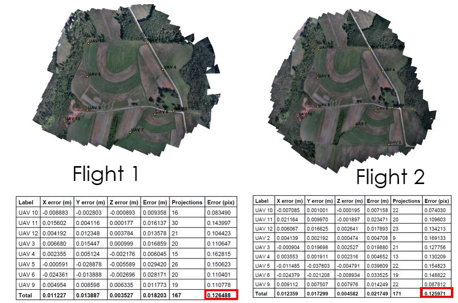
Survey data
Flight plans
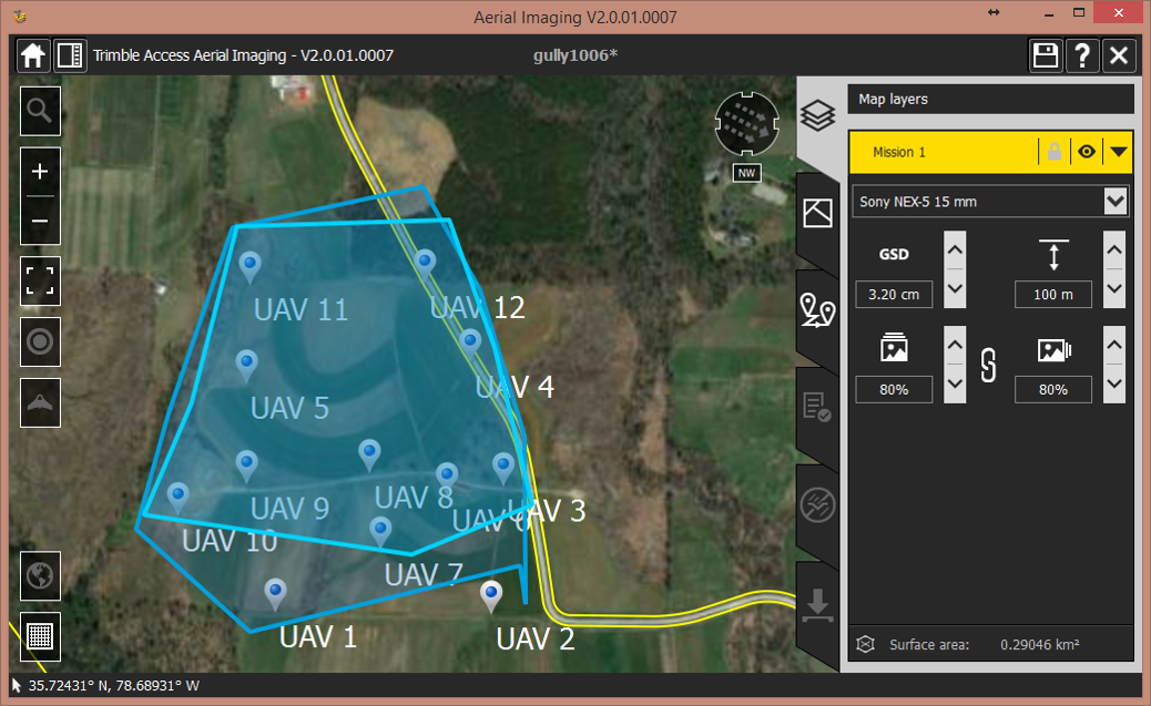
Flight plan – flight 1
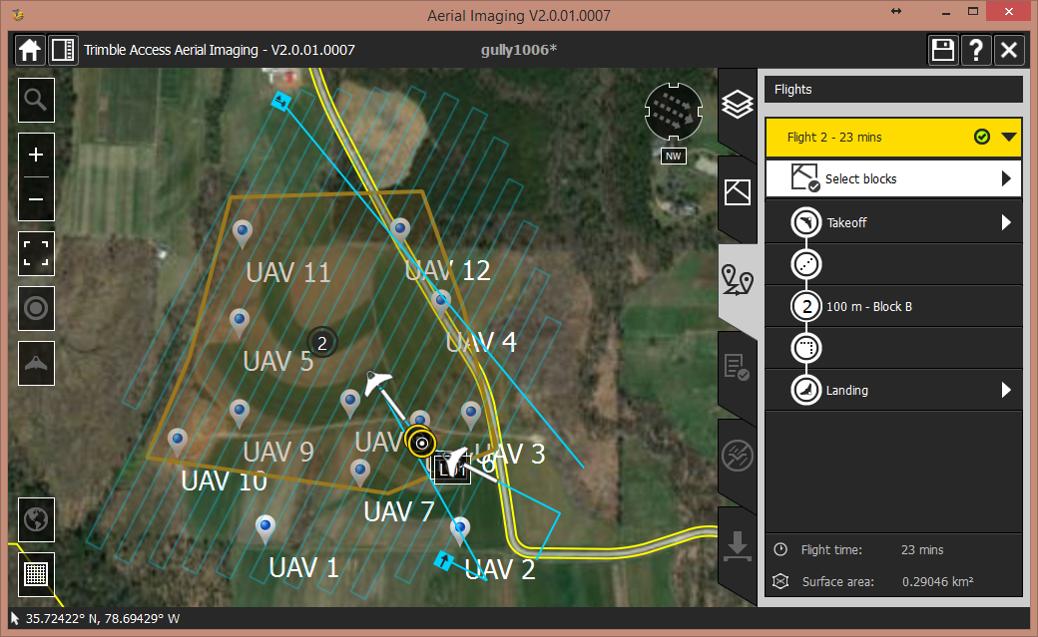
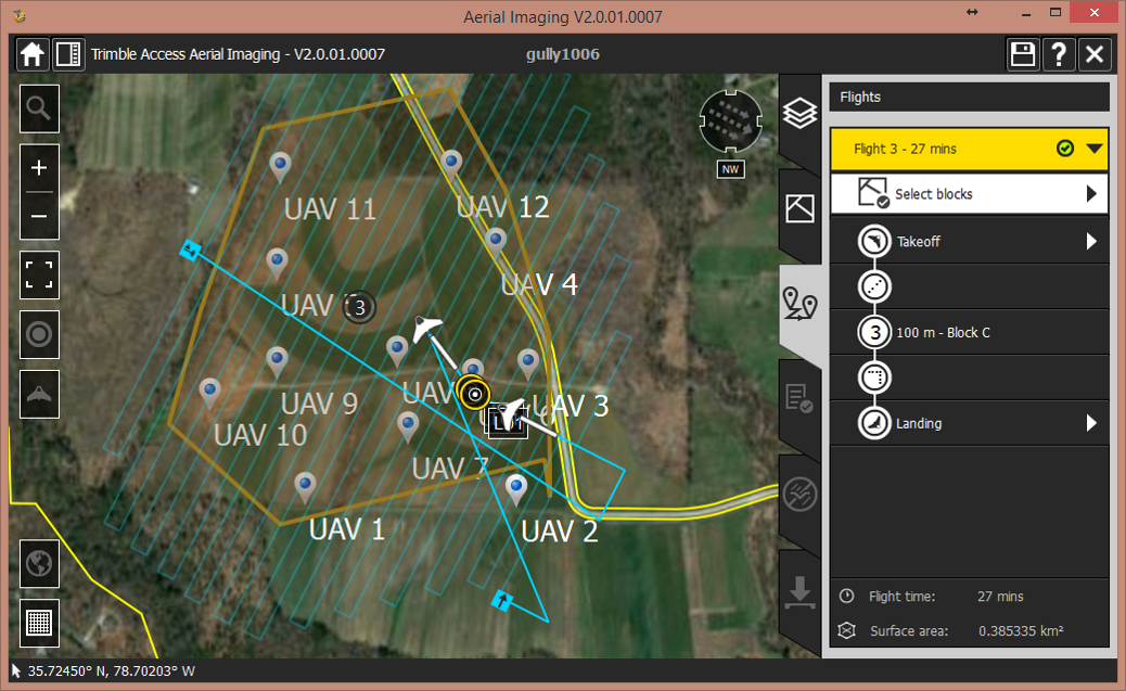
Flight plan – flight 2
Ground Control Points
Ground Control Points
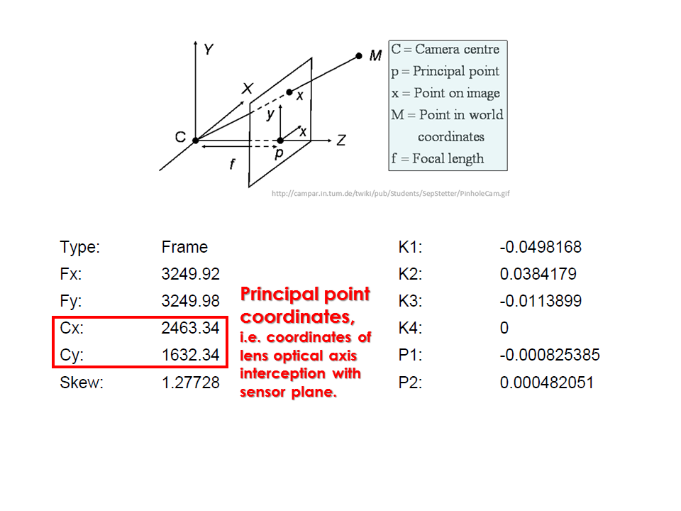
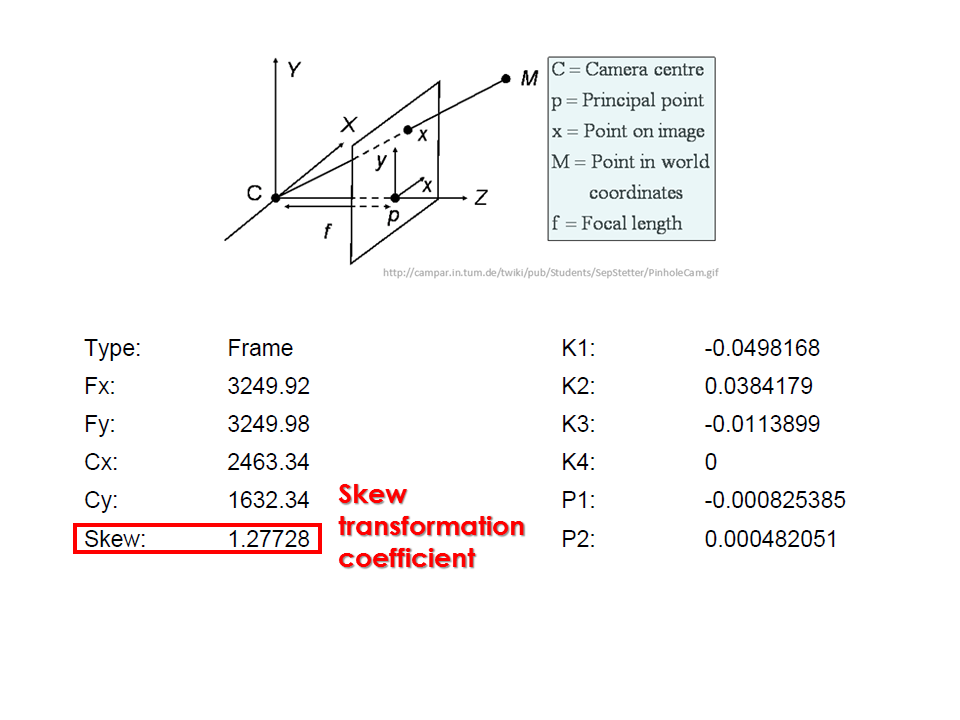
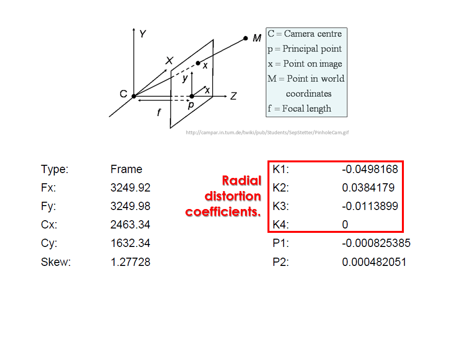
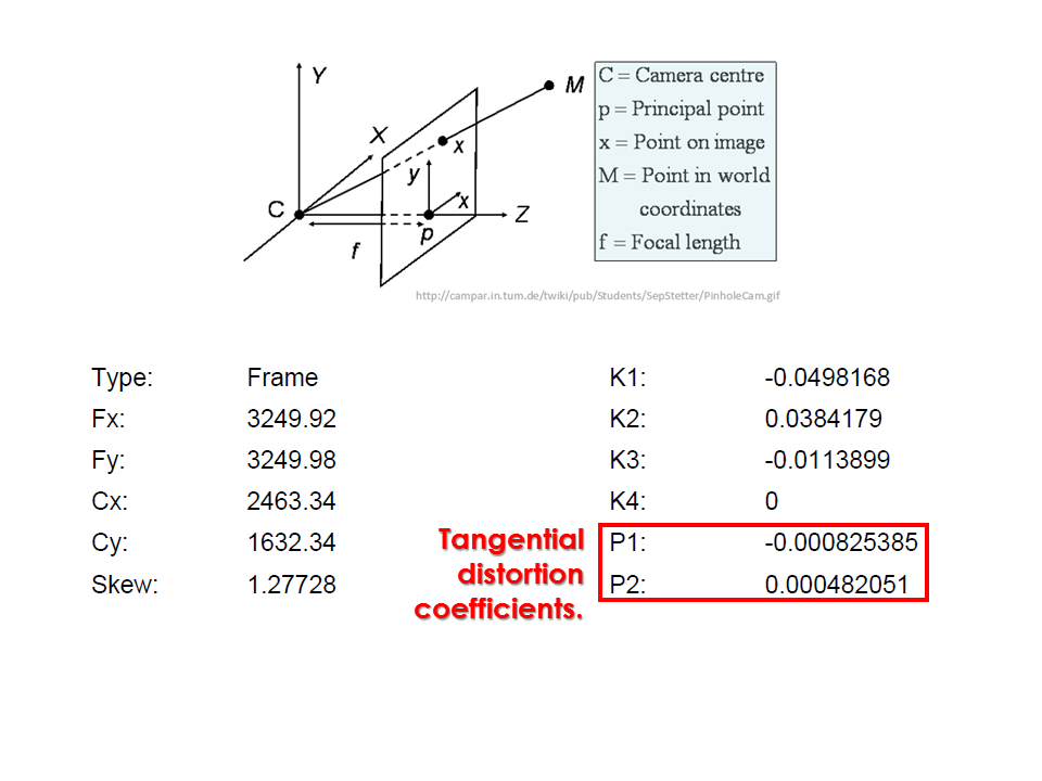
Camera calibration report
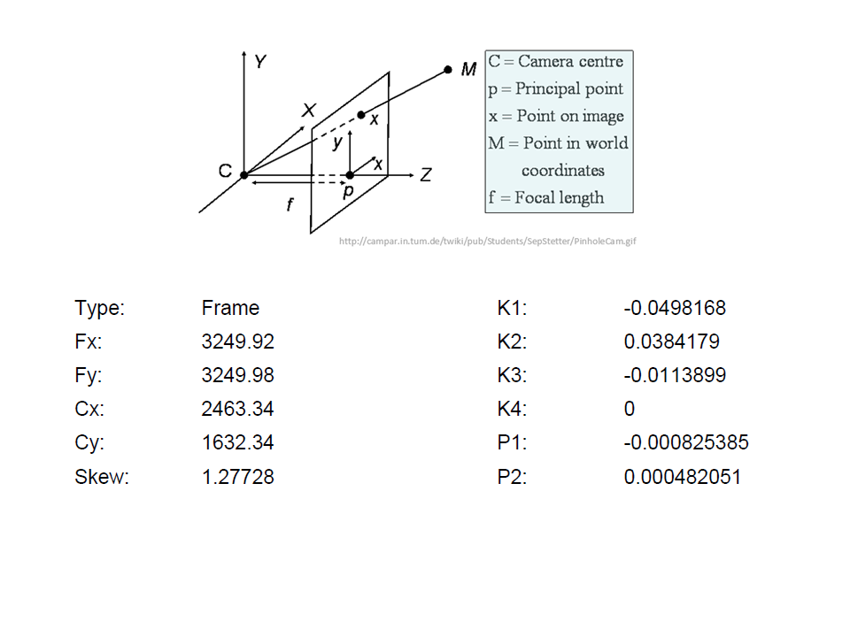
Camera calibration report
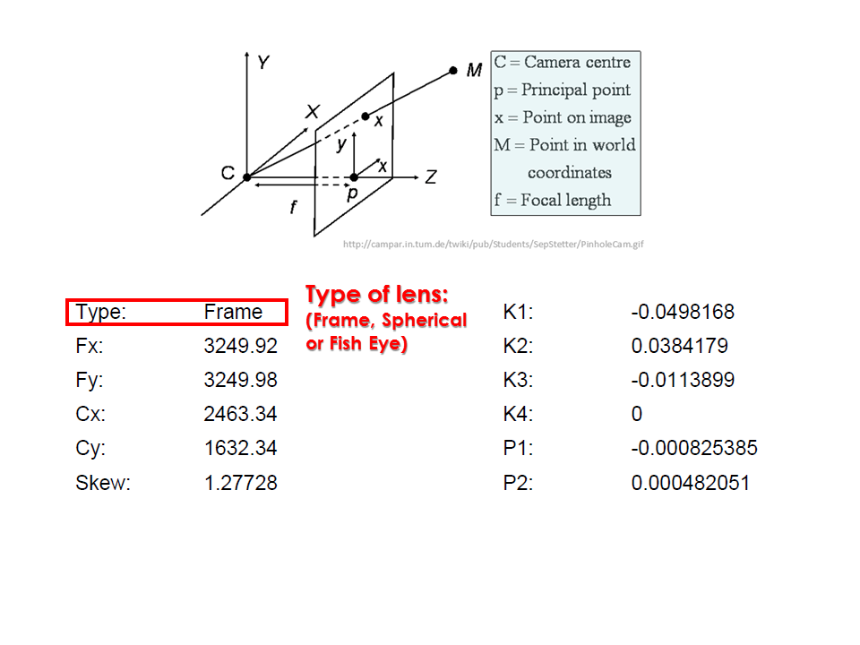
Camera calibration report
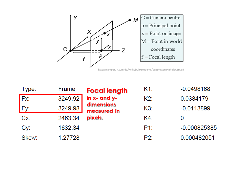
Camera calibration report
Camera calibration report
Camera calibration report
Camera calibration report
Analyzing the processing report
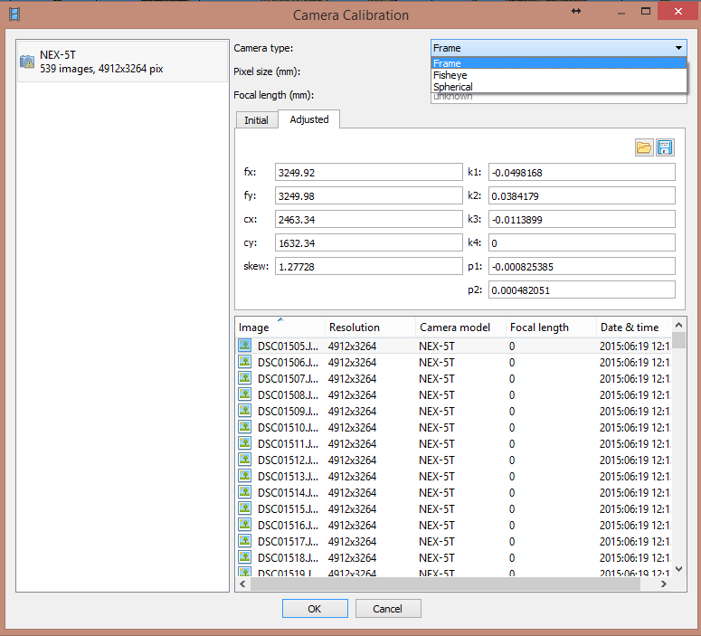
- While carrying out photo alignment PhotoScan estimates both internal and external camera orientation parameters, including nonlinear radial distortions.
Tools > Camera calibration
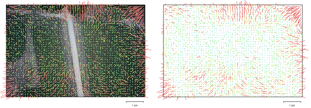
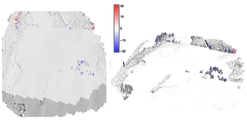
Image residuals
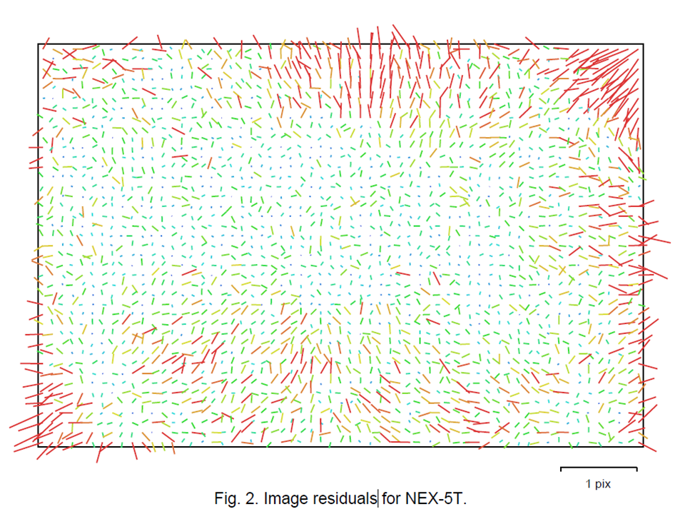
Image residuals
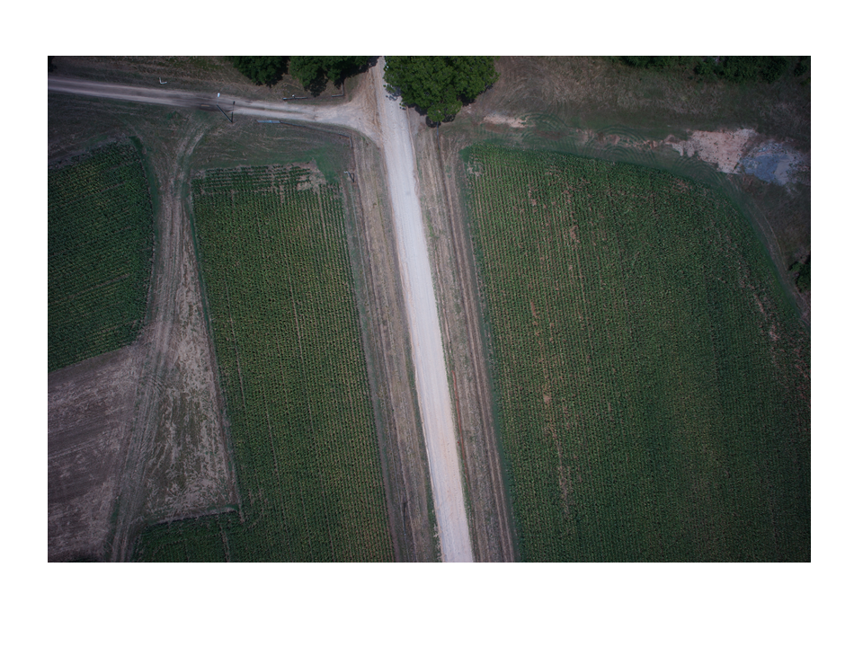
Image residuals
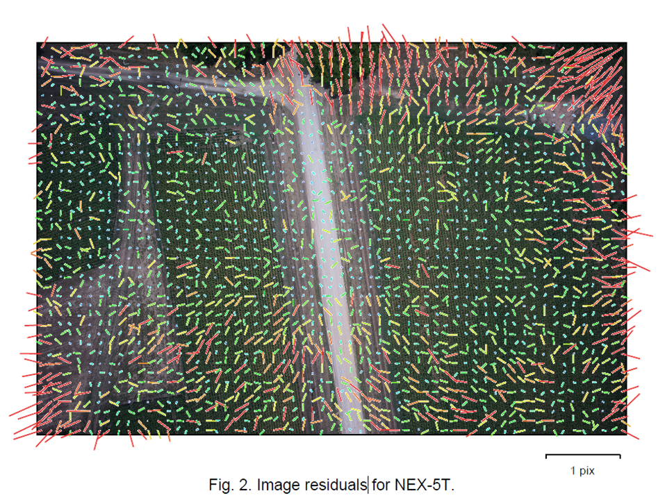
Image residuals
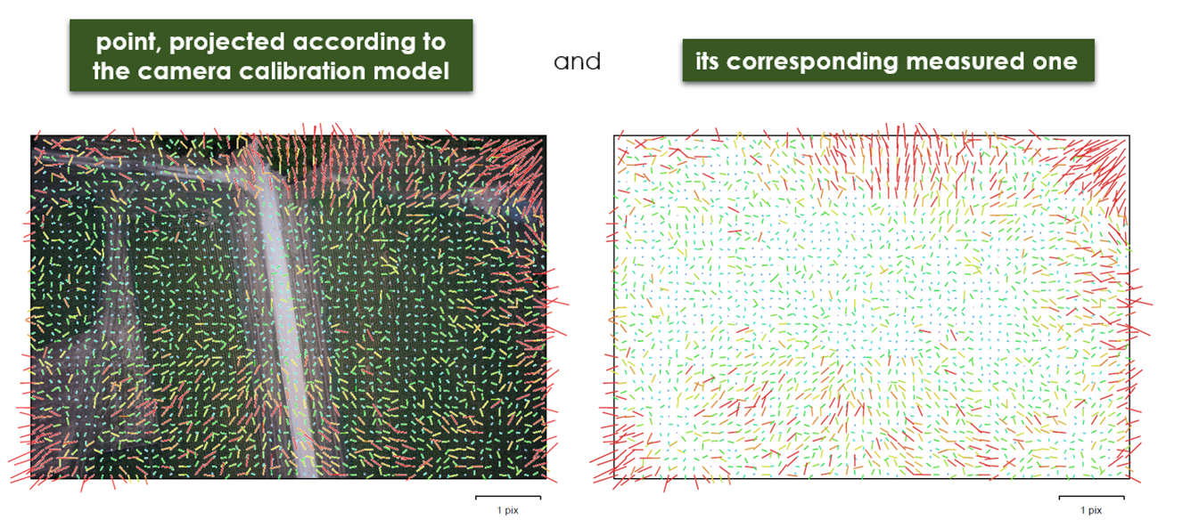
Image residuals
This reprojection error is equivalent to the root mean square (RMS) image residuals used in photogrammetric literature
More on image residuals in this article
Flight path
Flight path in 3D
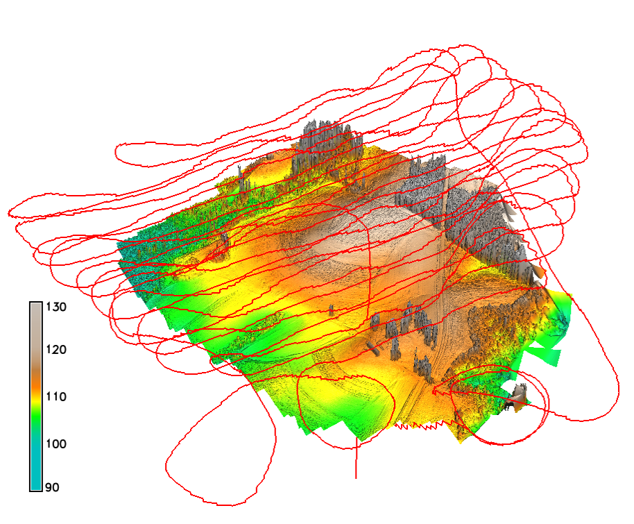
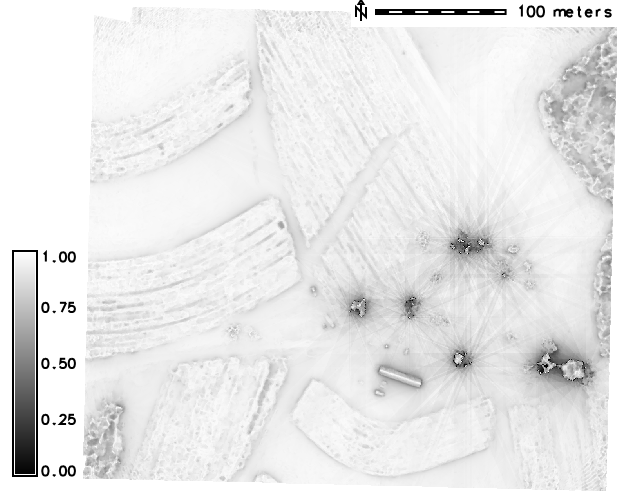
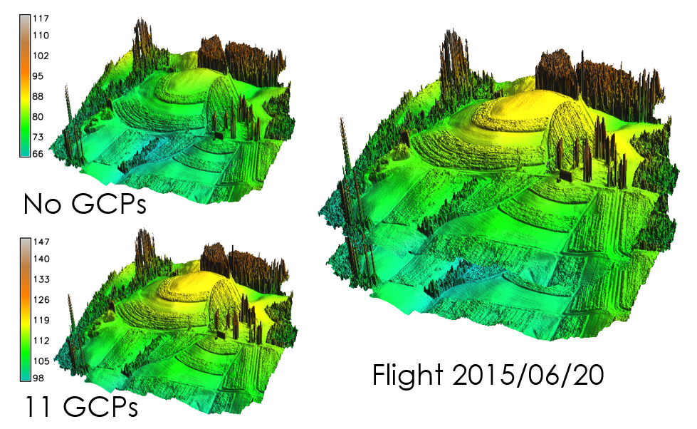
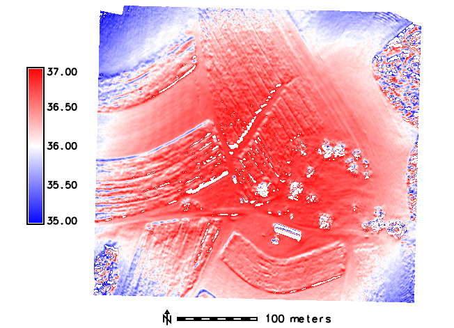
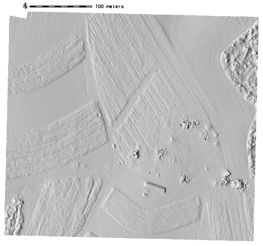
Digital Surface Model
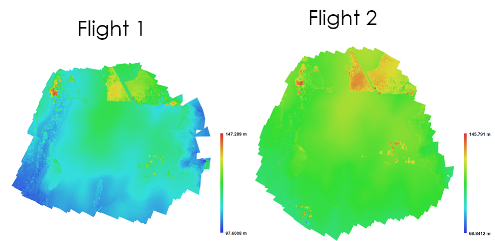
Digital Surface Model
Digital Surface Model
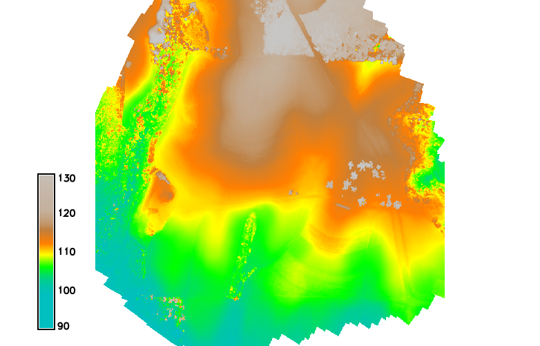
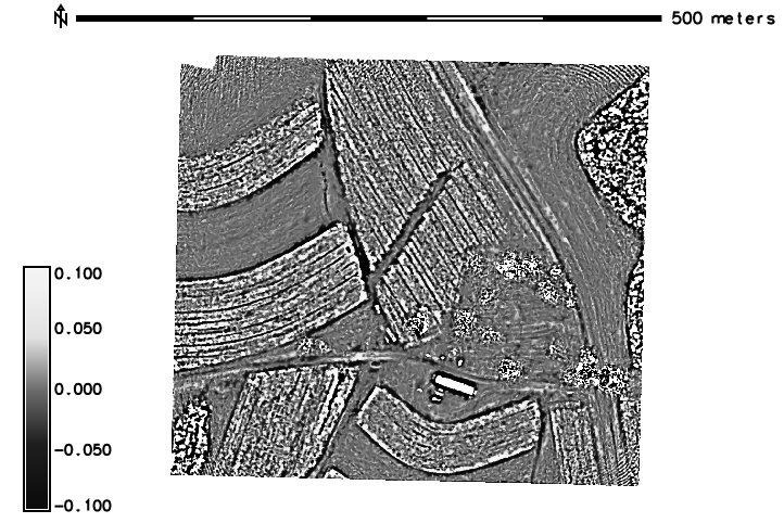
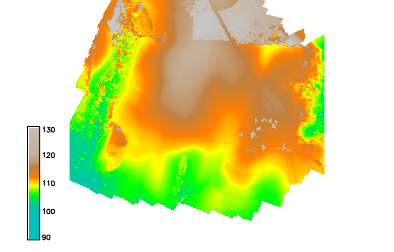
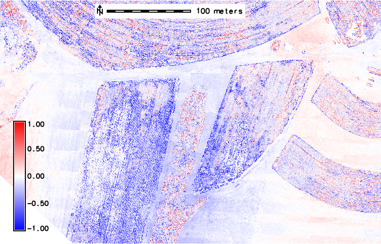
DSMs comparison
DSMs comparison by software
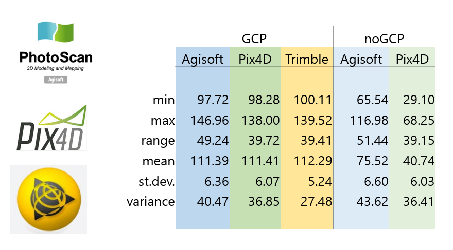
DSMs comparison -GCPs
'Bowl effect'
effect can be introduced during photo alignment, in case camera calibration estimates are inaccurate
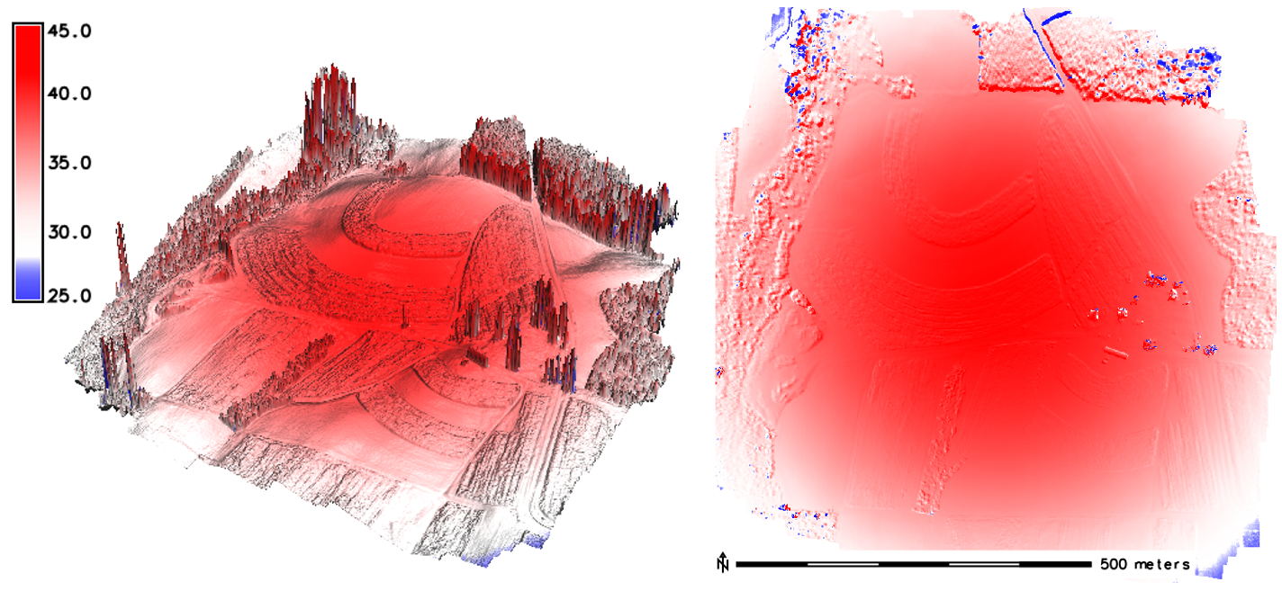
'Bowl effect'
effect can be introduced during photo alignment, in case camera calibration estimates are inaccurate
'Bowl effect'- solutions to the problem
- If camera calibration is known in advance- it can be loaded in PhotoScan and fixed during photo alignment.
- Optimization procedure - recommended approach
- based on camera or GCP coordinates
- performed after photo alignment
- is recommended to perform optimization based on ground control data in any case, even if precalibrated cameras are used
Optimization
What is an optimization?
- PhotoScan performs full photogrammetric adjustment taking into account additional constraints introduced by ground control data
- Extrinsic and intrinsic parameters for all cameras are optimized at this step, in contrast to the simple 7-parameter transform used for georeferencing by default
- Optimization helps to significantly improve accuracy of the final solution
More on the bowl effect in this article
Softeware related issues
Pix4D - Trimble, Agisoft - Trimble
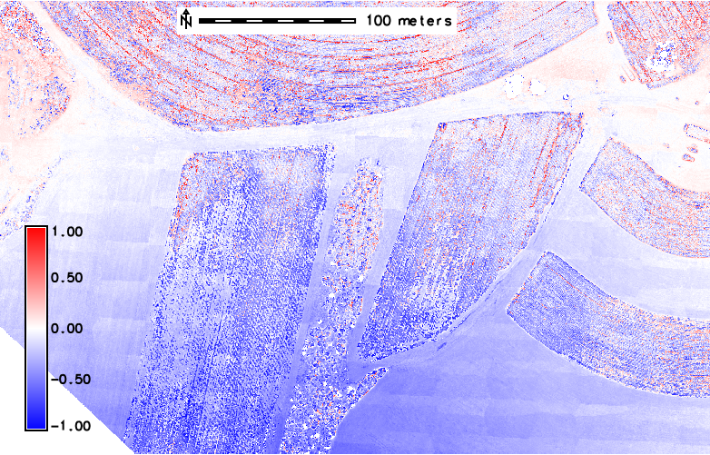
artifacts on Trimble DSM - "tiles" pattern visible for both cases
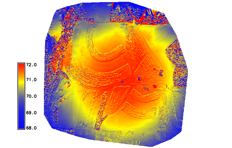
Softeware related issues
Pix4D - Agisoft, Agisoft - Trimble

artifacts on Trimble DSM - "tiles" pattern visible on Agisoft-Trimble (right), no artifacts on Pix4D-Agisoft (left)
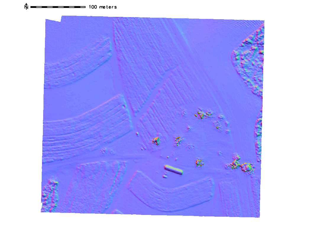
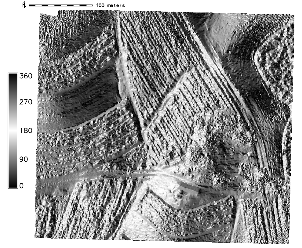
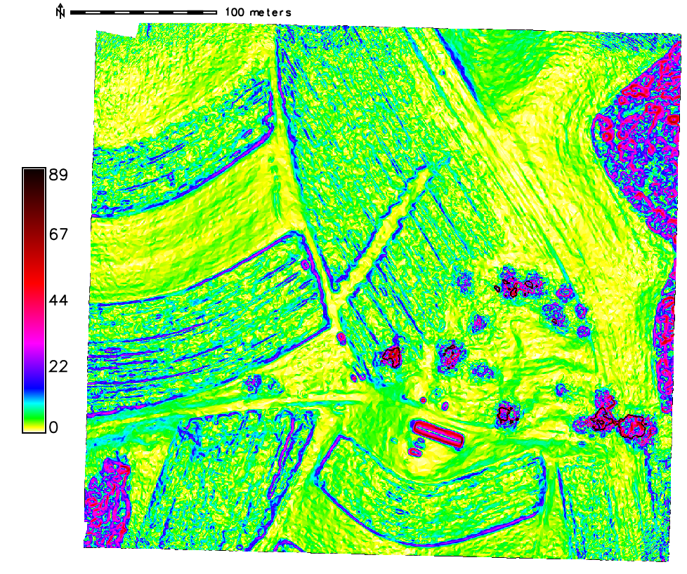
Terrain analysis
computing aspect, slope, curvature and shaded relief maps
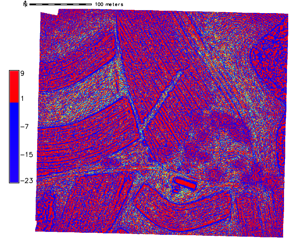
Advanced terrain analysis
computing local relief, skyview and shaded PCA maps